Author: Seungwoo Lee, Ph.D., P.E., S.E.
Publish Date: 23 Jun, 2022
Creep Analysis 7
Think about a two-span continuous bridge, as shown in Fig 1. Let’s calculate the secondary creep moments. Detailed dimensions and creep factors, etc., are not important, and the MIDAS file “Creep 2ndary Check” is attached for the reader’s reference.
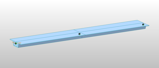
Fig 1 two-span bridge
Perform only the creep analysis, and the 2ndary creep moments at time=infinity are shown in Fig 2. We got 351 ft-kips at the pier location.
We know the 2ndary creep moments are linear between supports and the graph looks perfect.
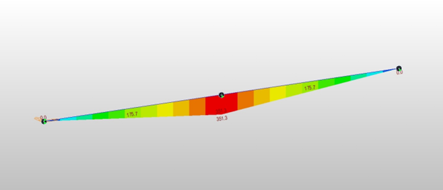
Fig 2 2ndary creep moment at time=infinity
Is this correct?
The 2ndary creep moments never occur if the sections are homogeneous and the support conditions remain the same.
What is wrong?
The 2ndary creep moments are due to dead load and the dead load moments are parabola, as shown in Fig 3.
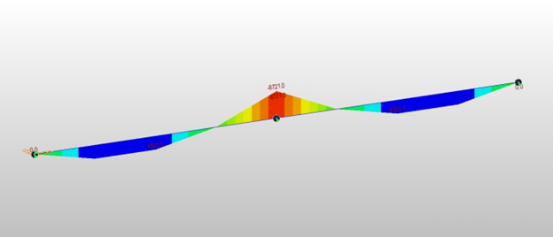
Fig 3 Dead load moment
The equivalent creep moments are calculated from creep deformation only at nodes, and it is assumed that these creep moments vary linearly between nodes. But this is not true in this parabola dead load moment case.
These are three ways we can solve this problem.
The first is considering these non-linear moment variation effects through some member loads. This looks like an exquisite way but only applies to a straightforward case like this example. In real problems, clarifying the moment variation within a member is not an easy task and only approximations in most cases.
The second way is to divide a single element into many elements and assume the moment variation is linear between nodes.
The problem is “how many elements”?
We can foresee that the 2ndary creep moments can be reduced to a quarter, 351.3/4 = 87.8 ft-kips if we divide an element into two elements because the moment varies in 2nd order. See Fig 4 and refer to MIDAS file “Creep 2ndary Check 2 Divisions”.
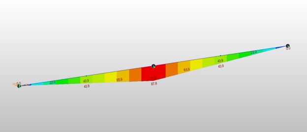
Fig 4 2ndary creep moment at time=infinity with 2 divisions
If we divide an element into four elements, the 2ndary creep moment would be reduced to 351.3/16 = 22.0 ft-kips, as shown in Fig 5 (Creep 2ndary Check 4 Divisions).
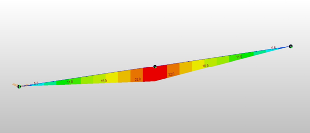
Fig 5 2ndary creep moment at time=infinity with 4 divisions
The author believes no more element division is justified considering the uncertainty of creep itself. Fig 6 shows the number of span divisions vs. 2ndary creep moment at the pier.
From the author’s personal experiences, if a maximum of ten element divisions between supports are not enough, it is better to check the model, not increase element division.
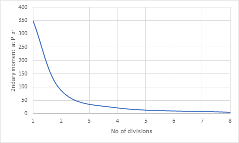
Fig 6 Number of span divisions vs. 2ndary creep moment at the pier
The third way is to make the dead load moment curve a linear one.
Fig 7 and Fig 8 show equivalent nodal dead load and corresponding dead load moment diagrams for 2 division cases. In this case, the 2ndary creep moments are perfectly zero at all locations. Check the model “Creep 2ndary Check 2 Divisions Point Loads”.
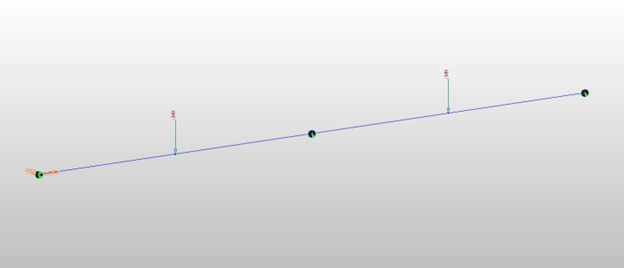
Fig 7 Equivalent dead load, 2 division case
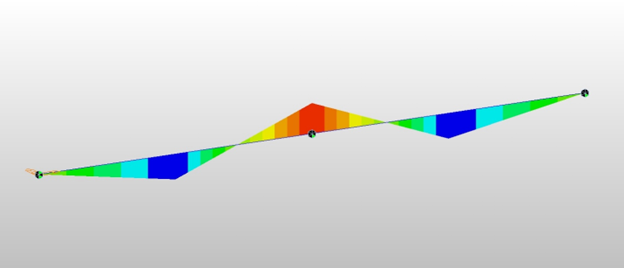
Fig 8 Dead load moment diagram, 2 division case
The problem is, in this case, the dead load moment itself is not correct due to insufficient element divisions.
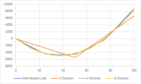
Fig 9 shows the number of span divisions vs. dead load moments. 4 division case produces less than 10% error, and the 8 division case produces less than 2% error. In real projects, the author believes a 2% error is acceptable.
Fig 9 Number of span divisions vs dead load moment
Recommendation
The scary part of displacement methods is that we can get wrong results without warning or error messages. The engineers should understand the program's theories and be able to interpret the output correctly.


Add a Comment