Author: Seungwoo Lee, Ph.D., P.E., S.E.
Publish Date: 12 Jul, 2021
A linear analysis is when a linear relationship is held constantly for the stress and strain of a model, meaning that the stiffness matrix of the model stays the same throughout the analysis. However, when can an analysis be called non-linear? What are the types of non-linear analysis? Seungwoo Lee, Ph.D., senior supervising engineer at WSP USA is here with us to talk about some basic types of non-linear analysis.
Q: What is linear and non-linear analysis?
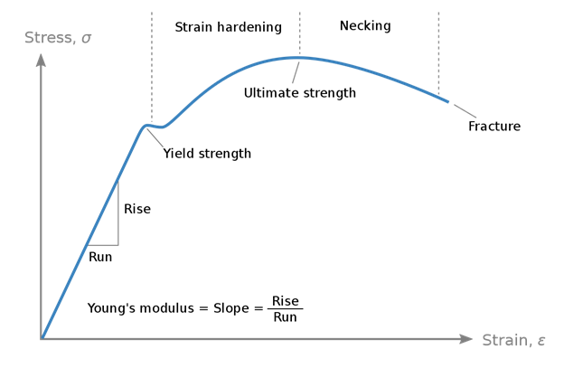
Lee: One of the best example is the stress-strain relationship shown in figure 1,

Figure 1. Stress-strain relationship (from Wikipedia).
The stress-strain relationship can be considered as linear only when the stress and/or strain is low. If the stress is higher than some level (yield strength in Figure 1), or the strain is larger than some value (the strain corresponding to yield strength in Figure 1), the stress-strain relationship is non-linear. This is normally classified as material non-linearity.
Q: Do we only need to consider material non-linearity for better approximation of analysis results?
Lee: There are more that engineers need to consider. Many have been and are considering two more non-linearity. The second is geometric non-linearity.

Figure 2. Deflections of a cantilever beam (from D. Singhal, et al., Large and Small Deflections Analysis of A Cantilever Beam, Journal of the Institution of Engineers).
The deflected beam in figure 2(a) represents the linear theory, which is also called the small deflection/deformation theory. The bending moment at the fixed support is M= PL and no axial force is present in the beam. Shear is constant along the beam. This serves as a relatively good approximation only if the deflection, u (or the rotation φ) is small, and this is why it is called the small deflection/deformation theory.
Figure 2(b) is the same as figure 2(a), but somewhat exaggerated. There is horizontal displacement ux and the moment at the fixed supports is now M = P (L - ux). Due to change in length, there is axial force in the beam, with that equals to Psin(φ0) at the tip. The shear is not constant along the beam, and the shear direction also varies. In the linear theory shown by the deflected beam in figure 2(a), the deflection uy is linearly proportional to the loading P. In other words, if P becomes 2P, the deflection is 2uy, if P becomes 3P, the deflection is 3uy, etc. In the non-linear theory shown by the deflected beam in figure 2(b), the above relationship is not true anymore. The relationship between P and uy is now non-linear.
The other non-linearity is constraint or contact non-linearity caused by boundary conditions.

Figure 3. Cantilever with gapped support (from Nam-Ho Kim, Finite Element Analysis of Contact Problem).
If the tip deflection due to load is less then δ, the structural system is a simple cantilever. Along with the load increase, the tip deflection increases, and at some point, the cantilever tip will hit the rigid block and the structural system is not a simple cantilever anymore. The degree of freedom of the system is constrained by an imposed boundary condition. Therefore, the simple cantilever system is now a beam with two different support conditions at its ends, which is caused by the model's boundary non-linearity.
Q: Are all these non-linearities independent from each other?
Lee: No. Analysis non-linearities are dependent. In most cases, large deflection/rotation occurs with large moments, and the section would yield or crack. In this case, material non-linearity would also be considered apart from geometric non-linearity.
Q: We live in 21st century with high-end computers. Why not consider all these non-linear effects together?
Lee: We can not and need not. Do we need to consider each gravel size and reinforcement details to calculate the reinforced concrete beam moment? Probably not although we may need to consider the crack effects if needed. The same thing for non-linear analysis. The exact (whatever it means) solution for non-linear analysis has not been formalized yet and is not needed. What we need is the approximates within allowable error.
Q: In what cases should we consider non-linearity?
Lee: It usually depends on what type of structure you are analyzing, but at least for the structure types below, non-linear analysis is usually a minimum requirement for reliable results.
-
-
-
-
-
-
-
-
-
-
-
-
-
-
-
-
- Columns
- Arch bridges
- Suspension bridges
- Cable-stayed bridges
-
-
-
-
-
-
-
-
-
-
-
-
-
-
-
The example shown below illustrates the non-linear relationship in the analysis results of a simple non-linear analysis. (Example taken from Goto, Shigeo, Tangent stiffness equation of flexible cable and some considerations, JSCE, Vol 270, September, 1978).For given cable system, a variable load P is applied. Calculate the vertical deflection at the loading point. Cable self-weight is 1.0 t/m, and cable axial stiffness is EA = 2,550,000 TON. The cable sag is calculated as 16.671 m before the application of the load P.

Figure 4. Cable structure with a load P applied.

Figure 5. Vertical deflection vs load increase.
Shown in figure 5, the relationship between deflection and the applied load is not linear. This non-linear displacement - load relationship means the stiffness of the system is dependent on the loading.


Add a Comment